In this project we will learn how to build a self driving car that avoid any obstacles.
Components needed
- Arduino Uno
- Jumper Cables
- 9 volt battery
- L298N Motor Driver
- 2 DC Motors
- 2 wheels
- 1 caster wheel
- Ultrasonic Sensor
What is an L298N Motor Driver?

The image above is an L298N Motor Driver. The L298N is a dual H-Bridge motor driver which allows the speed and the direction control of two DC motors at the same time. We can also use this motor driver to control one stepper motor.
| Pin | Usage |
|---|---|
| OUT 1 and OUT 2 | The OUT 1 and the OUT 2 pins are connected to motor A |
| OUT 3 and OUT 4 | The OUT 3 and the OUT 4 pins are connected to motor B |
| +12V (Vcc) | The +12V pin supplies power to the motor. It can be anywhere between 5V to 35V. |
| GND | The GND pin is for the ground and also needs to be connected to the Arduino board ground. |
| 5V | For the 5V pin, if the 5V-EN jumper is in place, this pin acts as an output and can be used to power up your Arduino. If the 5V-EN jumper is removed, you need to provide an external power supply to power up the Arduino board. |
| ENA | If the jumper is in place, motor gets full speed. If we want to control the speed of the motor, we need to remove the jumper and connect that pin to the PWM pin on the Arduino board as shown in the completed circuit. |
| IN1 and IN2 | The IN1 and the IN2 pins are both used to control the direction of motor A. If the IN1 pin is HIGH, and IN2 pin is LOW, the motor will spin forward. If the IN1 pin is LOW, and IN2 pin is HIGH, the motor will spin backward. If both pins are HIGH or if both pins are LOW, the motor will stop. |
| ENB | If jumper is in place, motor gets full speed. If we want to control the speed of the motor, we need to remove the jumper and connect that pin to the PWM pin on the Arduino board as shown in the completed circuit. |
| IN3 and IN4 | The IN3 and the IN4 pins are both used to control the direction of motor B. If the IN3 pin is HIGH, and IN4 pin is LOW, the motor will spin forward. If the IN3 pin is LOW, and IN4 pin is HIGH, the motor will spin backward. If both pins are HIGH or if both pins are LOW, the motor will stop. |
The table above shows the connections of the L298N module.
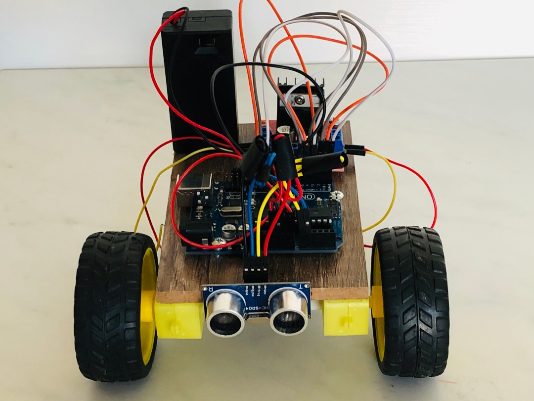
Completed Circuit

The Code
#include <HCSR04.h>


UltraSonicDistanceSensor ultrasonic(A0,A1);
float distance;

// left motor
int leftMotorSpeedPin = 3;
int leftMotorForwardPin = 4;
int leftMotorBackwardPin = 5;

// right motor
int rightMotorSpeedPin = 11;
int rightMotorForwardPin = 12;
int rightMotorBackwardPin = 13;


void setup() {
    pinMode(leftMotorSpeedPin, OUTPUT);
    pinMode(leftMotorForwardPin, OUTPUT);
    pinMode(leftMotorBackwardPin, OUTPUT);
    pinMode(rightMotorSpeedPin, OUTPUT);
    pinMode(rightMotorForwardPin, OUTPUT);
    pinMode(rightMotorBackwardPin, OUTPUT);

    Serial.begin(9600);

  digitalWrite(leftMotorSpeedPin, HIGH);
  digitalWrite(rightMotorSpeedPin, HIGH);

}

void loop() {

  distance = ultrasonic.measureDistanceCm(); //Use 'CM' for centimeters or 'INC' for inches
  Serial.println(distance);

  if (distance > -1 && distance < 25) {
    stop();
    delay(1000);
    goBackward();
    delay(300);
    stop();
    delay(1000);

    if(random(0, 2) == 0) {
      goLeft();
    } else {
      goRight();
    }

    delay(500);
    stop();
    delay(700);
  } else {
    goForward();
  }


}

void goForward() {
  digitalWrite(leftMotorForwardPin, HIGH);
  digitalWrite(leftMotorBackwardPin, LOW);
  digitalWrite(rightMotorForwardPin, HIGH);
  digitalWrite(rightMotorBackwardPin, LOW);
}

void goBackward() {
  digitalWrite(leftMotorForwardPin, LOW);
  digitalWrite(leftMotorBackwardPin, HIGH);
  digitalWrite(rightMotorForwardPin, LOW);
  digitalWrite(rightMotorBackwardPin, HIGH);
}

void stop() {
  digitalWrite(leftMotorForwardPin, LOW);
  digitalWrite(leftMotorBackwardPin, LOW);
  digitalWrite(rightMotorForwardPin, LOW);
  digitalWrite(rightMotorBackwardPin, LOW);
}

void goRight() {
  digitalWrite(leftMotorForwardPin, HIGH);
  digitalWrite(leftMotorBackwardPin, LOW);
  digitalWrite(rightMotorForwardPin, LOW);
  digitalWrite(rightMotorBackwardPin, LOW);
}

void goLeft() {
  digitalWrite(leftMotorForwardPin, LOW);
  digitalWrite(leftMotorBackwardPin, LOW);
  digitalWrite(rightMotorForwardPin, HIGH);
  digitalWrite(rightMotorBackwardPin, LOW);
}
The video below shows a quick demonstration of the self driving arduino car.

Hi.
Nice and easy to follow building instruction.
One thing i noticed is the image of the Arduino used in the ‘Completed Circuit’ diagram. It shows the Ethernet Shield instead the Arduino uno. It should not be a big problem since the power, digital and analog pins are at the same position.
Sincerely
LikeLike