Components needed
- Photoresistor
- LED
- Resistors
- Jumper cables
- Arduino Uno board
- Breadboard
- A USB Cable
- A computer with the Arduino IDE installed
Completed Circuit
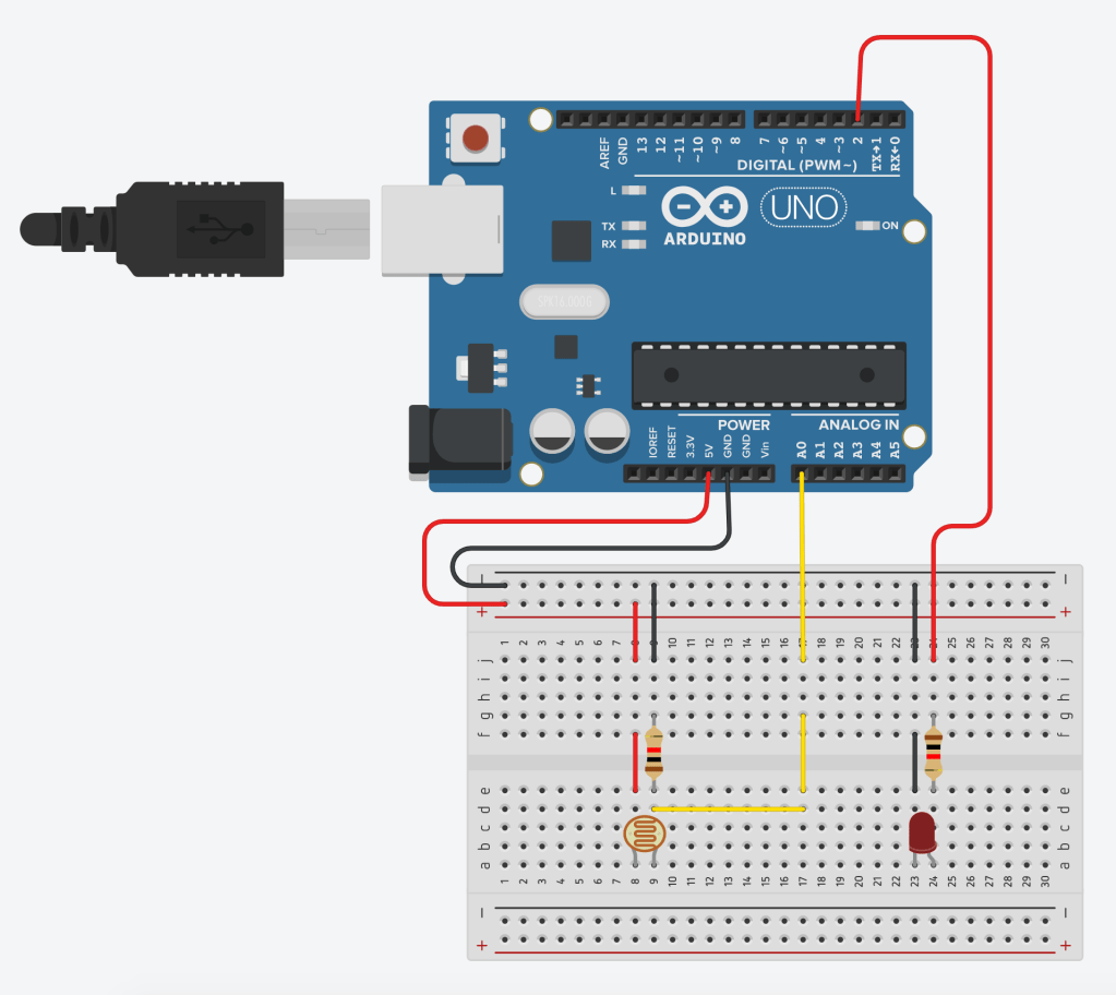


The circuit above shows the use of a photoresistor. As we learned in the previous blog, the resistance changes in potentiometer by turning the knob. Similarly the resistance in of the photoresistor changes based on light. More the light, less the resistance, and more resistance in the dark.
To show the variable resistance in photoresistor by light, we put LED on the board. LED’s brightness changes as the resistance changes. A photoresistor is a very simple component with two pins. One for power and one for ground. Ground pin is connected to analog pin (A0) where we can read the value of voltage coming across the photo resistor using analogRead function. See program and explanation below for more information.
The Program
int photo_resister;

void setup()
{
 pinMode(A0, INPUT);
 pinMode(2, OUTPUT);
}

void loop()
{

  photo_resister = analogRead(A0);

  if (photo_resister > 300)
  {
    digitalWrite(2, LOW);
  }
  else
  {
    digitalWrite(2, HIGH);
  }

}
This is a very simple program. We are declaring the variable called photo_resistor in the beginning. Then in the setup function, we are setting up pin A0 for INPUT, and setting up pin number 2, for OUTPUT.
In the loop function, we are reading from pin A0, and then storing the value of the voltage coming out of photo resistor into the photo_resistor variable. As explained earlier, full voltage will pass through photo resistor in full light and minimal voltage will pass through photo resistor in complete dark as resistance changes based on light intensity. That’s why photo resistor is also called LDR, Light Dependent Resistor. Finally, we are turning the LED on if the photo_resistor value is less than 400, and turning the LED off, if the photo_resistor value is greater than 400.
This means that in the dark, the LED will turn on, and in the light, the LED will turn off. Please watch the video below for the demo of the circuit. Please do not hesitate to ask any questions in the comment below.

hi Aarav, Great work. I had to read about how photo register works. Also, I have to correct you here and make sure you get it right. As light turns brighter, resistance decreases in photo register. You are measuring the voltage on two ends of the register after photoregister. So, if light increases, voltage will increase increase across the other resister. Let me know if it makes sense or not. I am sorry if I couldn’t get my point across by writing, You can watch this video to understand what I mean https://www.youtube.com/watch?v=iNea_HM967A
LikeLike
Thanks Divyesh uncle. I think we are talking about same thing. If resistance increases, voltage decreases and if resistance decreases, voltages increases. I have programmed it that way to turn light on and off. Thanks for sharing video.
LikeLike