
LCDs are fun and we can use them in Arduino projects to show status messages or to display information like temperature or distance or any value instead of showing them in the serial monitor. In this tutorial we will learn how to connect 16×2 character LCD to Arduino board and how to display information on it.
What is an I2C LCD?
I2C stands for Inter-Integrated Circuit. Standard LCDs typically require about 12 connections if you want to use it fully to use all its features. Our whole circuit will look complicated and we need to program each pin. It will also require more pins on the Arduino board.
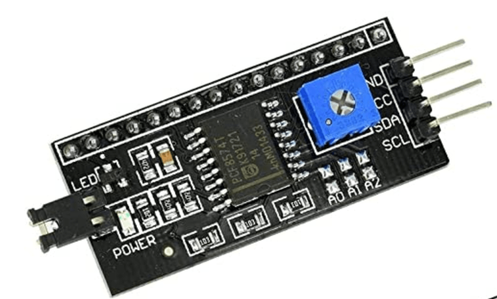
In this tutorial, we will use I2C LCD. I2C LCD comes with a small circuit on the back of the LCD. This circuit has a PCF8574 chip and a built in potentiometer to adjust the LCD backlight. Using the I2C LCD is very simple. We only need two data pins (analog pins) to control the LCD. The picture below is the add on circuit you will find on the back of the I2C LCD. The blue colored cube shaped component is the potentiometer, to control the brightness of the LCD.
If you have the standard LCD, you can buy this add on circuit separately, and easily make your standard LCD into an I2C enabled LCD. Here is the link to buy it from amazon.
The picture below is showing the 16×2 LCD. If you look closely, you can see 16 small rectangles on two lines, hence it is called a 16×2 LCD.

Each rectangle is made up of 5×8 pixels. We can control individual pixels of those rectangles and create custom characters too. We will talk about that in another blog.
Components needed
- I2C LCD display
- DHT11 Temperature Sensor
- Jumper cables
- Arduino board
- USB cable
- A computer with the Arduino IDE installed
Completed circuit

The program
https://create.arduino.cc/editor/aaravpatel0124/589168fd-e665-4395-a4d8-748be07f0e53/preview
#include <Wire.h>
#include <LiquidCrystal_I2C.h>

#include <DHT.h>
#include <DHT_U.h>

LiquidCrystal_I2C lcd(0x27,16,2);  // set the LCD address to 0x27 for a 16 chars and 2 line display

DHT dht(7, DHT11);

float tempInFarenheit;
float tempInCelcius;

void setup()
{
  lcd.init();
  dht.begin();

  // Print a message to the LCD.
  lcd.backlight();

}


void loop()
{
  tempInCelcius=dht.readTemperature();
  tempInFarenheit=tempInCelcius*9/5+32;
  delay(1000);
  lcd.clear();
  lcd.setCursor(0,0);
  lcd.print("Temperature:");
  lcd.setCursor(0,1);
  lcd.print(tempInFarenheit);
  lcd.setCursor(6,1);
  lcd.print("F");
}
The connections
The connections for the I2C LCD display is fairly simple. Their are 4 wires we need to connect. 2 of them are for the ground and the power. The other 2 pins are for the SDA and the SCL. The SDA is the Serial Data pin. This pin carries and transmit the data that is going from the Arduino board to the LCD display. The SCL is the Serial Clock pin. This pin synchronizes the data transfer. Just like the shift register, it “clocks” data into the LCD. Both of these pins are connected to the analog pins on the Arduino board.
| GND | GND |
| VCC | 5V |
| SDA | A4 |
| SCL | A5 |

One thought on “I2C LCD Module Display”